
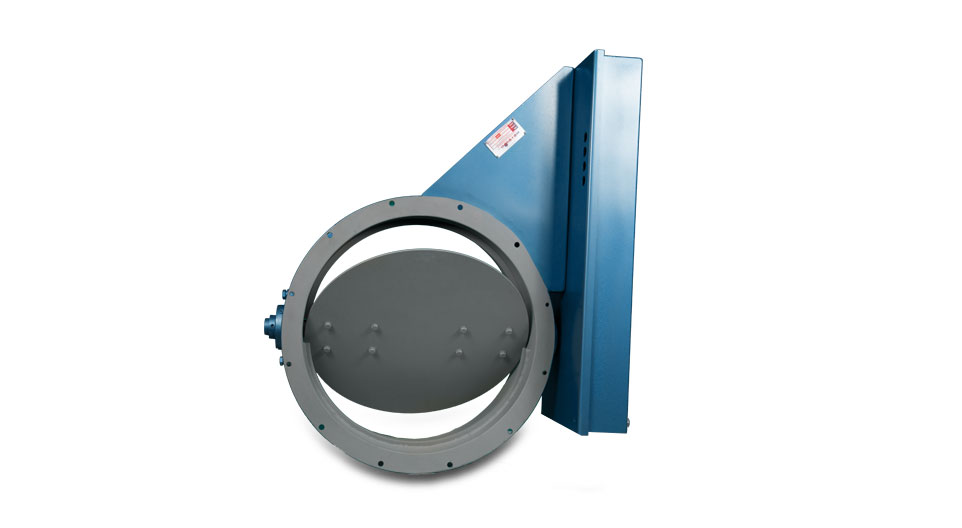
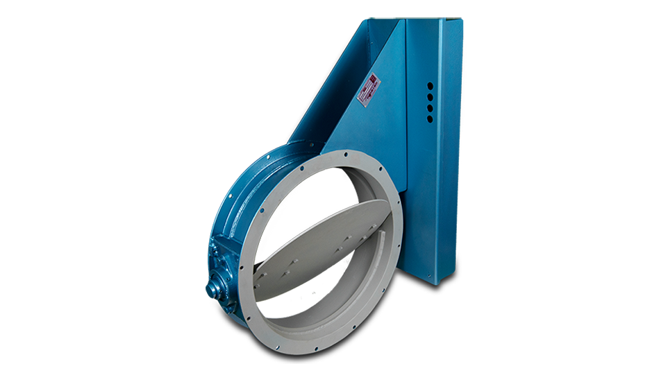
The fabricated range of Rotolok Butterfly Dampers are used extensively in the air and dust handling industries generally in fan systems.
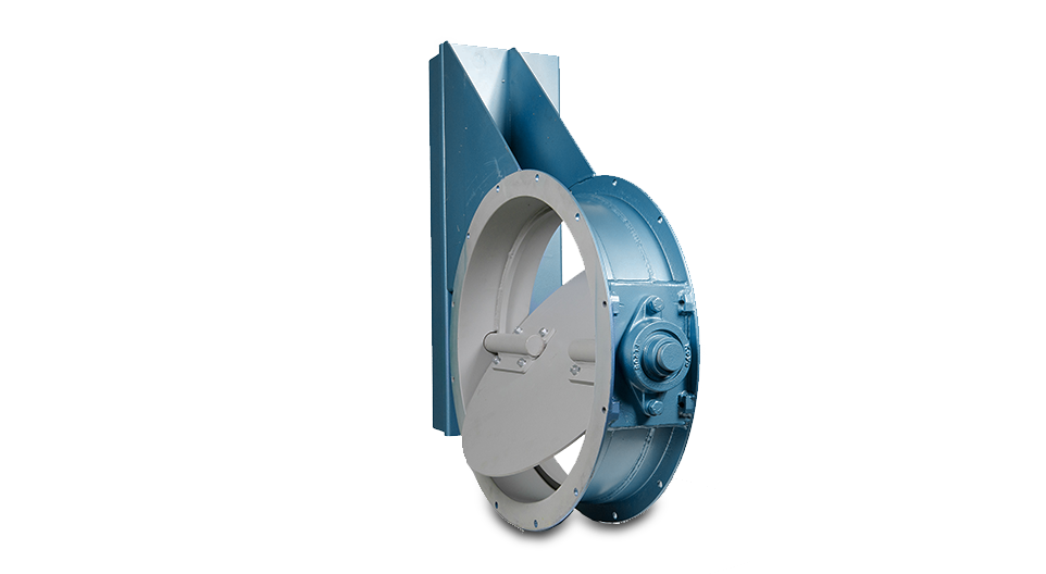
They are normally operated remotely by air cylinders, electric or pneumatic actuators, although manual versions through the customary hand lever, handwheel and reduction gearboxes can be accommodated.
Construction is generally from Mild or Stainless Steel with the body of the valve formed from rolled steel angles or
channels dependent on the size.
The Damper itself is formed from two plates which sandwich, if required, a felt seal or alternatively it can be a single
blade sized for close fitment to the valve body. The type selected is dependent on the amount of air leakage that can be
accepted.
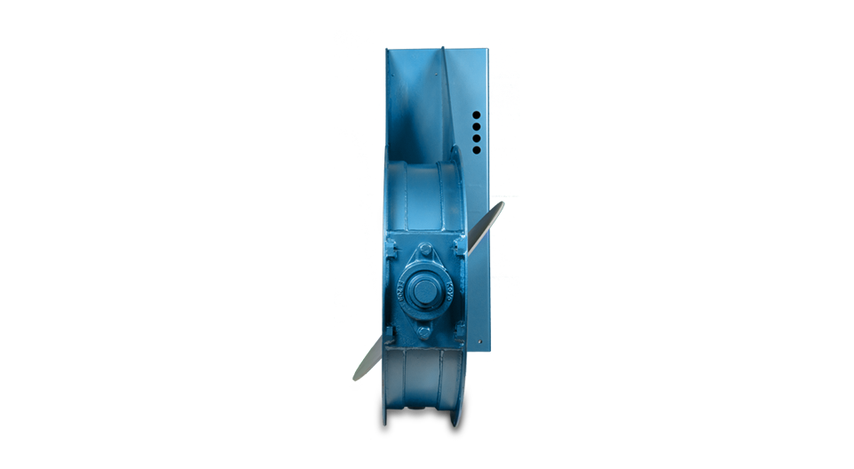
The split spindle mounting system minimizes turbulence within the air stream and these spindles are mounted on either two
or four bolt flanged mounted sealed for life bearings.
Seals can be fitted if required through a simple ‘O’ ring or, on high temperature applications, the conventional stuffing
box is utilised.
The type of actuator, to suit the clients requirements or specification, can be added to all sizes and, on pneumatic
versions, limit switches and single solenoid spring return valves are included.
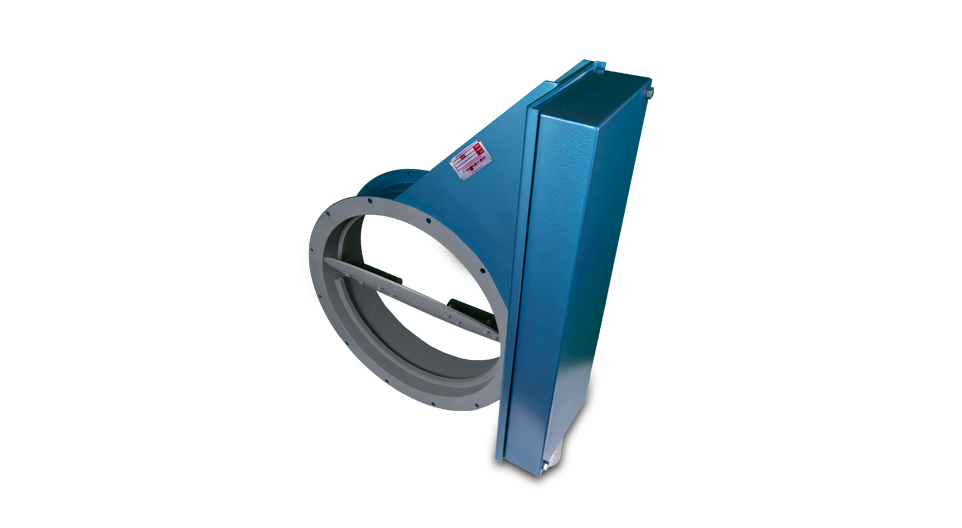
With fabrication, practically any size can be accommodated to suit the duct size with flanges also made to suit system
designers needs.
The range starts at 350mm diameter and extends to 1500mm in diameter. Standard sizes are as shown in the chart
below. Square units and special sizes can be, and have been supplied.
On valve size selection it is important to ensure that the ducting size is equal to or slightly larger than the valve. This is to
prevent any possible interference during the damper operation in the area where the blade enters the ducting, or should
there be any misalignment between the components on assembly.
All dimensions are in mm unless otherwise stated
| SIZE | A | B | C | D | E | F | G | H | K | L |
|---|---|---|---|---|---|---|---|---|---|---|
| 350 | 350 | 440 | 130 | 200 | 342 | 590 | 8 | 10 | 406 | 6 |
| 400 | 400 | 490 | 130 | 200 | 367 | 590 | 12 | 10 | 456 | 6 |
| 450 | 450 | 540 | 130 | 200 | 392 | 590 | 12 | 10 | 506 | 6 |
| 500 | 500 | 610 | 150 | 200 | 427 | 590 | 12 | 12 | 566 | 6 |
| 600 | 600 | 710 | 150 | 200 | 477 | 590 | 16 | 12 | 666 | 6 |
| 700 | 700 | 810 | 150 | 200 | 527 | 590 | 16 | 12 | 766 | 6 |